

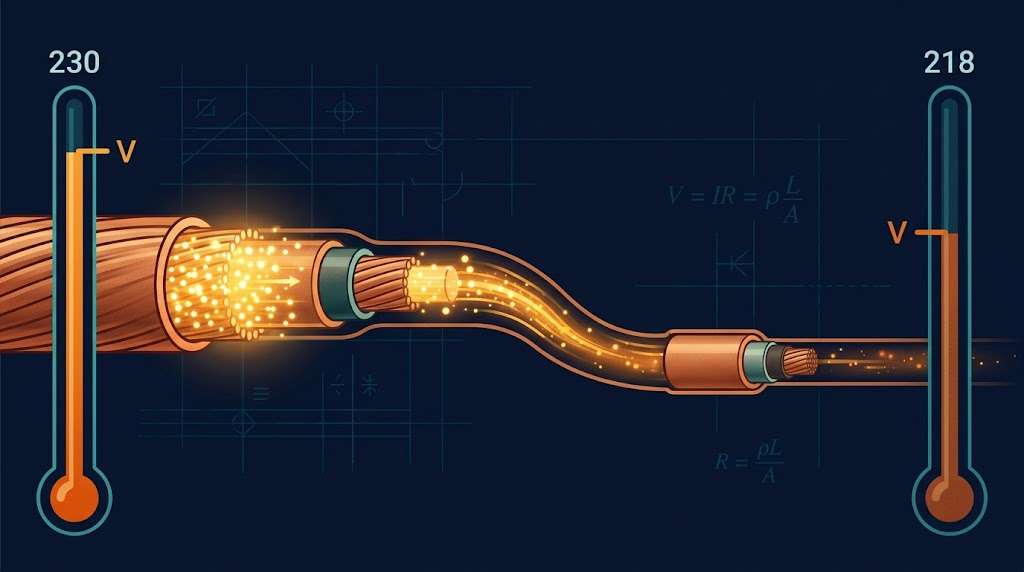

You connect equipment to a 230 V supply, run the numbers and expect 230 V at the far end. Then you measure at the terminals with the equipment running, and the reading is lower.
Is the supply at fault? Usually not. The cable is doing what every cable does.
Every conductor has resistance, even copper. When current flows through it, some voltage appears across the cable itself and is no longer available to the equipment. That is voltage drop.
On a short run you will barely notice it. On a long run carrying a heavy load, it can decide whether a motor starts or a light looks dim. This guide covers how to calculate it, how to judge the result and where people go wrong.
What Voltage Drop Actually Is
Think of a lighting circuit. Power leaves the distribution board, travels along a cable and reaches the fitting. The cable is not a perfect conductor, so part of the supply voltage is spent pushing current along it.
What arrives at the fitting is lower than what left the board. That gap is the voltage drop.
It is a normal effect, not proof of faulty wiring. The trouble starts when it gets too large. Lights dim, motors struggle and sensitive electronics can misbehave if the supply falls outside its working range.
Where Most People Get Stuck
Series versus parallel. In a series circuit the same current passes through every component, so voltage splits by resistance. A 10 Ω resistor drops twice the voltage of a 5 Ω resistor. In an ideal parallel circuit, every branch sees the same voltage while the currents differ.
Current is not used up. A resistor does not consume current. What flows in flows out. The potential difference changes, not the current.
The return conductor. This one catches people constantly. Equipment 30 m from the supply does not mean 30 m in your equation. In a two-wire circuit the current goes out and comes back, so the loop is 60 m.
Loaded versus unloaded readings. With little or no load current, the voltage difference between the two ends of the cable is usually very small. Connect a substantial load, however, and the resistance produces a more noticeable drop. Always measure under working conditions.
When people look for Electrical Engineering Coursework Help Online, it is often because a result looks right but they cannot justify it. These four points are where those marks quietly disappear, because markers want you to explain why a result changes, not just substitute numbers.
The Three Ideas Behind Every Calculation
Ohm’s law: V = I × R. A 5 Ω resistor carrying 3 A drops 15 V. Raise the current to 4 A and it drops 20 V. Same resistor, bigger drop.
Kirchhoff’s voltage law. Around any closed loop, the voltage rises and drops sum to zero. Take a 24 V supply across 4 Ω and 8 Ω in series. Total resistance is 12 Ω, current is 2 A, and the drops are 8 V and 16 V. Together they make 24 V.
If your drops do not add up to the supply, look for an arithmetic slip or a misread circuit.
Conductor resistance: R = ρL ÷ A. Here ρ is resistivity, L is length and A is cross-sectional area. Double the length and you double the resistance. Double the area and you halve it.
So two cables carrying identical current can drop different voltages purely because of their size or material.
A Worked Example
Take a two-wire copper cable, 20 m one way, 2.5 mm², carrying 10 A from a 230 V supply. Use ρ = 1.68 × 10⁻⁸ Ω·m, the value at 20°C.
Step 1: total length. Out and back is 20 + 20 = 40 m.
Step 2: convert the area. 2.5 mm² = 2.5 × 10⁻⁶ m². Skip this and your answer is wrong by a factor of a million.
Step 3: resistance. R = (1.68 × 10⁻⁸ × 40) ÷ (2.5 × 10⁻⁶) = 0.2688 Ω.
Step 4: voltage drop. Vd = 10 × 0.2688 = 2.688 V. The load receives about 227.3 V, a drop of 1.17%.
Now raise the current to 15 A. The drop becomes 4.03 V. The cable has not changed. The load has.
Heat matters too. P = I²R = 10² × 0.2688 = 26.88 W, lost as heat in the cable. Voltage drop and power loss are linked, but they are not the same quantity.
The Step Most Guides Skip: Work Backwards From the Limit
Coursework usually asks for the drop. Real design asks a different question: how far can I run this cable?
In the UK, Appendix 4 of BS 7671:2018+A4:2026 recommends limits of 3% for lighting and 5% for other uses on an installation supplied from the public 230 V network. For lighting, 3% of 230 V is 6.9 V.
Treat these as design recommendations, not a pass-or-fail test for one cable. The allowance runs from the origin of the installation to the equipment, so any drop in an upstream submain uses part of it first.
For a simple check, rearrange the sums. At 10 A, the maximum loop resistance is 6.9 ÷ 10 = 0.69 Ω. A 2.5 mm² copper conductor at 20°C has about 0.00672 Ω per metre, so the out-and-back loop is 0.01344 Ω per metre of run.
Divide 0.69 by 0.01344 and you get roughly 51 m.
Now allow for heat. If we assume the conductor runs at 70°C, copper resistivity rises to about 2.01 × 10⁻⁸ Ω·m, around 20% higher. The same sums give roughly 43 m.
That 8 m gap is the whole point. A calculation at 20°C can pass a cable that fails in service. Not every cable reaches 70°C, so state the temperature you assumed and say why.
Both figures are resistance-only estimates. Real selection uses the tabulated mV/A/m values from the standard, which also cover reactance and power factor on AC circuits, plus installation method and other design checks.
Mistakes to Avoid
- Using one-way length. You halve the resistance and understate the drop.
- Splitting voltage equally. That only works when the resistances match.
- Applying series rules to parallel branches. Parallel branches share the same terminal voltage.
- Mixing units. Convert mm² to m² before substituting.
- Ignoring temperature and load. Fixed textbook values rarely match a working installation.
- Choosing the thickest cable by default. Current rating, protection and installation method matter too.
Bringing It Together
A lower voltage at the end of a cable is not automatically a fault. Most of the time it is simply resistance doing its job.
Ohm’s law gives you the drop. Kirchhoff’s law checks your loop. Resistivity explains why length, material and size change the answer.
Before you calculate, trace the full current path, check your units and state your assumptions. Then ask whether those assumptions match the real operating conditions.
Being able to calculate the number is useful. Being able to explain what it means for the equipment on the end of the cable is what marks you out as an engineer.